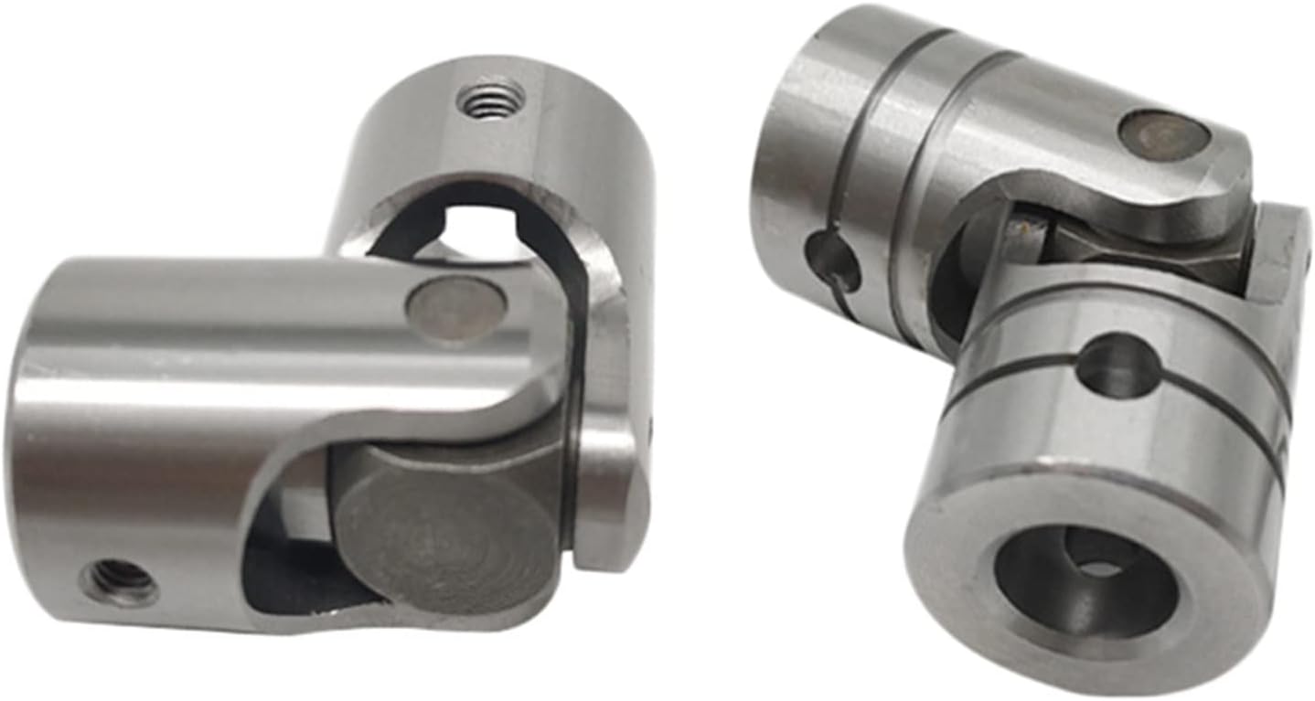
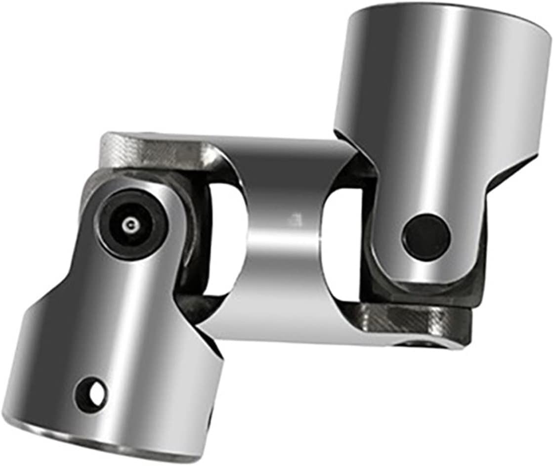
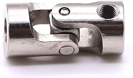
Product Description
| Product Name | Cardan Shaft |
| Product Model | SWC-I75A-335+40 |
| Main Material | 35CrMo or 45# Steel |
| Nominal Torque | 500 N.M |
| Normal Length | 335 mm |
| Length Compensation | 40 mm |
/* January 22, 2571 19:08:37 */!function(){function s(e,r){var a,o={};try{e&&e.split(“,”).forEach(function(e,t){e&&(a=e.match(/(.*?):(.*)$/))&&1

Phasing in Cardan Couplings and Its Impact on Performance
The concept of phasing in cardan couplings refers to the alignment of the universal joints’ yokes or flanges on the input and output shafts. Proper phasing is essential to minimize angular misalignment and maintain smooth rotational motion. When the yokes of the universal joints are not aligned correctly, it can result in uneven torque transmission, increased wear, and vibrations.
Phasing affects the performance of cardan couplings in several ways:
- Uniform Torque Transmission: Proper phasing ensures that torque is evenly distributed between the input and output shafts, reducing the risk of overloading individual universal joints.
- Reduced Vibrations: Correctly phased universal joints minimize angular misalignment, which helps reduce vibrations and noise in the machinery system.
- Extended Lifespan: Improved phasing leads to reduced wear and stress on the universal joint components, extending the overall lifespan of the coupling.
- Efficient Power Transmission: Proper phasing contributes to efficient power transmission by minimizing energy losses due to misalignment.
To achieve proper phasing, manufacturers often provide guidelines or marks on the coupling components to ensure accurate alignment. It’s essential to follow these guidelines during installation and any maintenance or adjustments to maintain optimal performance and reliability of the cardan coupling.

Materials Used in Manufacturing Cardan Couplings
Cardan couplings, also known as universal joints or u-joints, are crucial components in mechanical systems that transmit torque and accommodate angular misalignment. These couplings are manufactured using a variety of materials to ensure durability, reliability, and performance. Common materials used in the manufacturing of cardan couplings include:
1. Steel: Steel is a widely used material due to its high strength, durability, and resistance to wear and corrosion. Alloy steels are often chosen for their enhanced mechanical properties and fatigue resistance.
2. Cast Iron: Cast iron is used in some cardan couplings, especially in older or heavier-duty applications. It provides good strength and vibration dampening properties.
3. Aluminum: Aluminum is chosen for its lightweight properties, making it suitable for applications where weight reduction is important. It is commonly used in industries such as automotive and aerospace.
4. Stainless Steel: Stainless steel is used when corrosion resistance is a critical factor. It is commonly employed in environments where the coupling may be exposed to moisture or corrosive substances.
5. Bronze: Bronze can be used in certain applications where self-lubricating properties are desired. It also provides good wear resistance.
6. Synthetic Polymers: Some modern cardan couplings use synthetic polymers or plastics in their construction to reduce weight and provide specific performance characteristics, such as dampening vibrations.
The choice of material depends on factors like the application requirements, operational conditions, torque transmission, operating speed, and environmental factors. Manufacturers select materials that offer the best combination of strength, durability, wear resistance, and corrosion resistance for the specific use case of the cardan coupling.

Accommodation of Angular Misalignment in Shaft with Cardan Coupling
A cardan coupling, also known as a universal joint or u-joint, is designed to accommodate angular misalignment between two shafts while maintaining a constant velocity transfer. Here’s how it works:
The cardan coupling consists of two yokes or fork-like components, each attached to the end of a shaft. These yokes are connected by a cross-shaped central component called the cross or spider. The spider has bearings at its four ends that fit into grooves in the yokes.
When the connected shafts are misaligned at an angle, the spider allows the yokes to pivot around their respective shafts. This pivoting action of the yokes and the spider enables the coupling to transmit torque between the shafts even when they are not perfectly aligned. The spider’s bearings allow smooth rotation and transfer of power.
The design of the cardan coupling ensures that even during angular misalignment, the rotational speed remains consistent between the input and output shafts. However, it’s important to note that while cardan couplings can accommodate angular misalignment, they introduce a small amount of radial and axial movement, which can lead to fluctuating torque and vibration.
Cardan couplings are commonly used in applications where there is a need to transmit torque between shafts that are not in line, such as in drivetrains, vehicle suspensions, and industrial machinery.


editor by CX 2024-04-24