Product Description
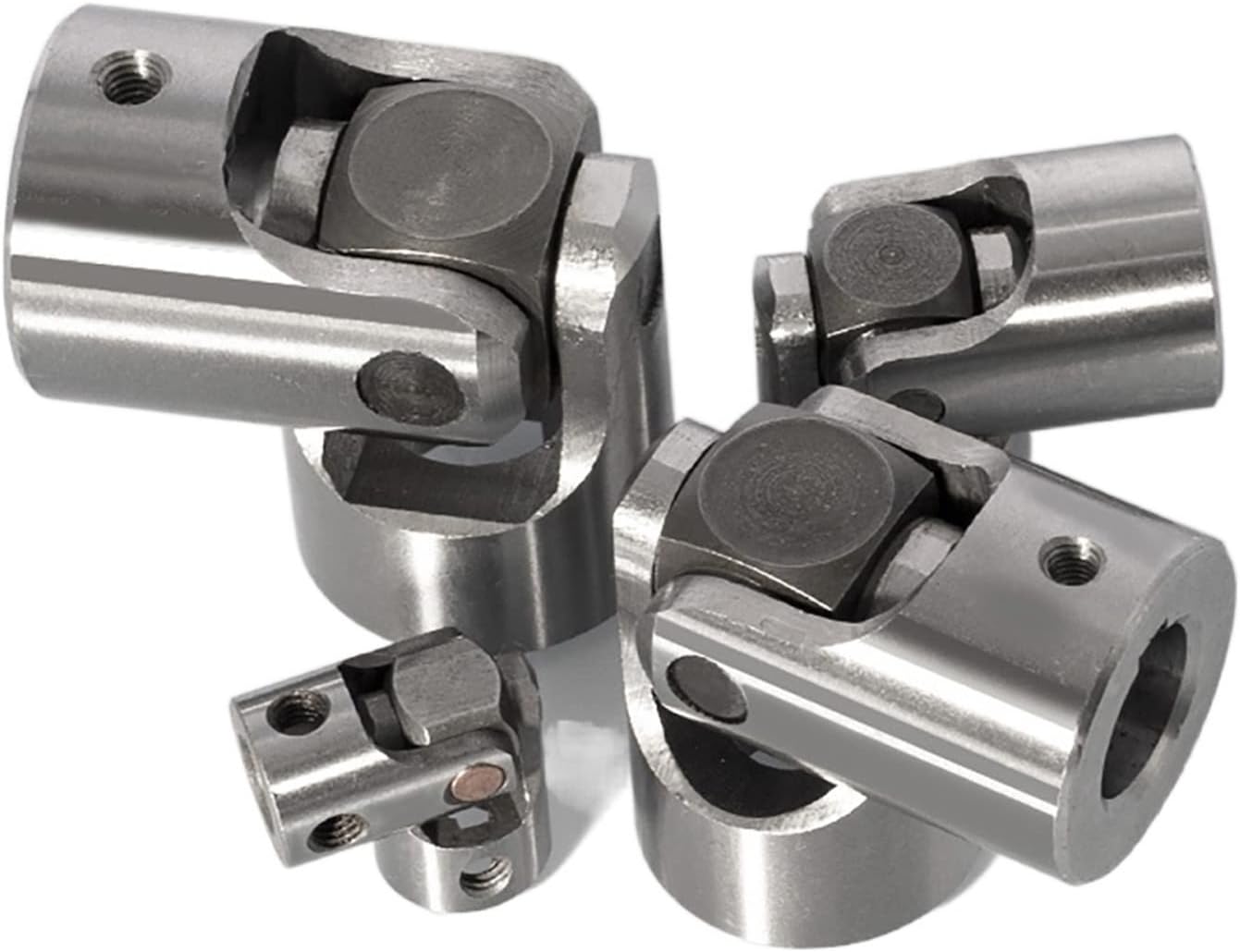
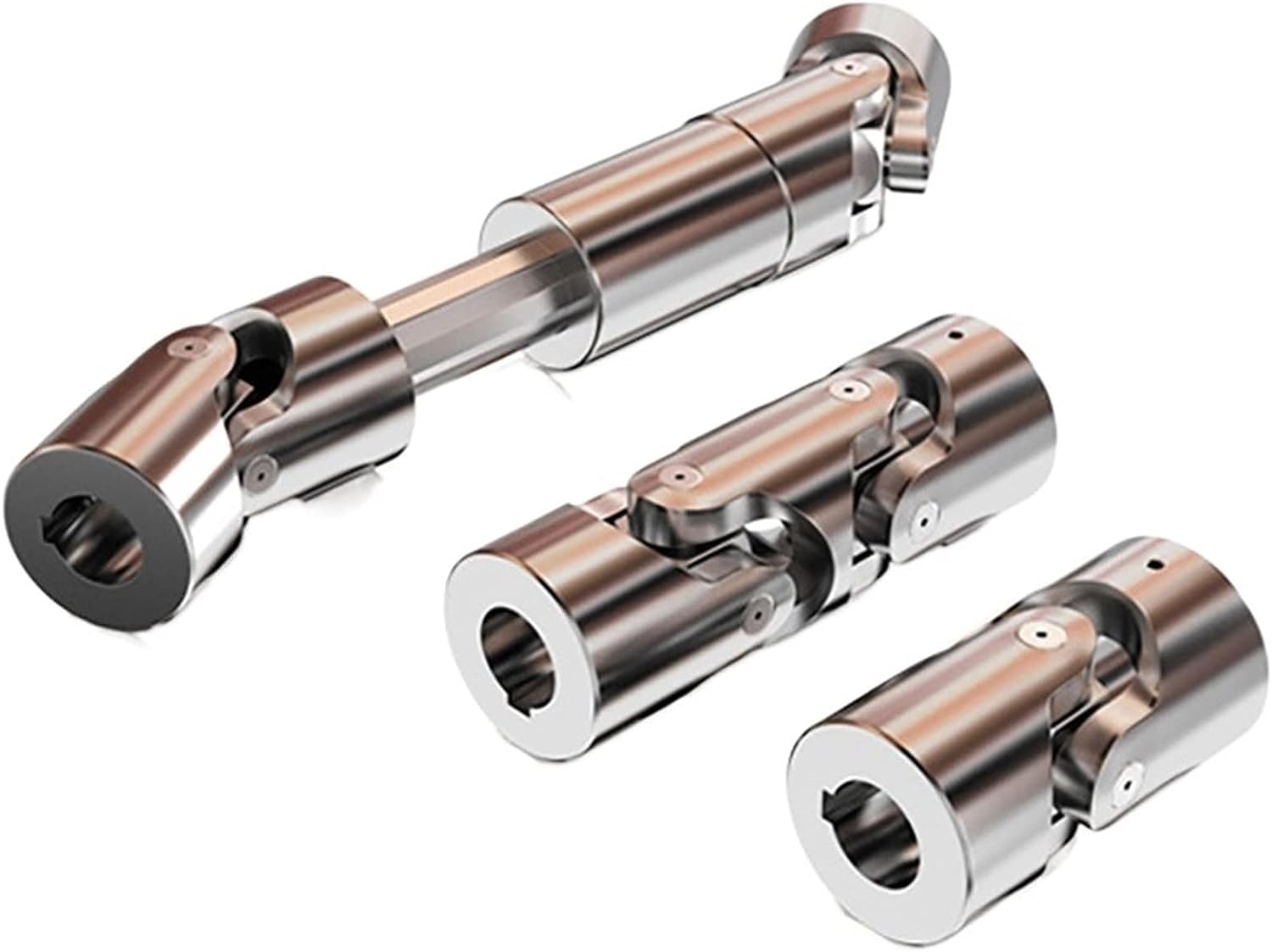
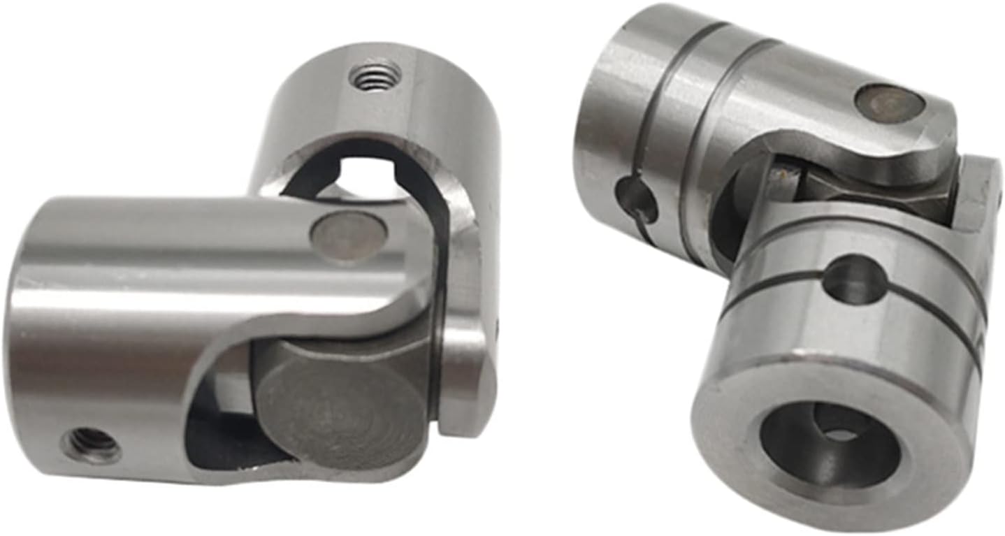
Welded Transmission Shaft Telescopic Universal Coupling SWP-A Ball Coupling
Description:
The SWP-A long flexible welded universal joint is a Universal joint designed to transmit power between 2 misaligned shafts. It is a flexible coupling, which means it can compensate for misalignment up to 25 degrees. The SWP-A long bend welded universal coupling is made of 35CrMo material and comes in various sizes to meet the needs of different applications. SWP-A long bend welded universal couplings are widely used in mechanical applications such as rolling mills, punches, straighteners, crushers, ship transmissions, papermaking equipment, ordinary machinery, water pump equipment, test benches, etc.
SWP-A Long Flexible Welded Universal Coupling Features:
1. Possess the ability to compensate for large angles.
2. The structure is compact and reasonable. The SWP-A universal coupling is equipped with an integrated fork, making it more reliable in carrying capacity.
3. Carrying capacity. Compared to other types of rotating joint shafts with the same diameter, it provides more torque, limits the turning diameter of mechanical equipment, and has a wider range.
4. High transmission efficiency. Its transmission efficiency is 98-99.8%, suitable for high-power transmission and has energy-saving effect.
5. Smooth carrying, low noise, easy disassembly and maintenance.
| Type | Tactical diameter D mm |
Nominal torque Tn kN·m |
Fatique torque Tf kN·m |
Axis angle β (°) |
Stretch length S mm |
Size(mm) | Rotary inertia kg·m2 |
Mass kg |
|||||||||||
| Lmin | D1 js11 |
D2 H7 |
D3 | E | E1 | B×h | h1 | L1 | n-d | Lmin | Increase 100 |
Lmin | Increase 100 |
||||||
| SWP160A | 160 | 16 | 8 | ≤10 | 50 | 660 | 140 | 95 | 114 | 15 | 4 | 20×12 | 6 | 85 | 6-13 | 0.13 | 0.0059 | 47 | 2.1 |
| SWP180A | 180 | 20 | 10 | ≤10 | 60 | 752 | 155 | 105 | 121 | 15 | 4 | 24×14 | 7 | 95 | 6-15 | 0.22 | 0.0072 | 60 | 2.3 |
| SWP200A | 200 | 31.5 | 16 | ≤10 | 70 | 823 | 175 | 125 | 17 | 17 | 5 | 28×16 | 8 | 110 | 8-15 | 0.37 | 0.0114 | 81 | 3.4 |
| SWP225A | 225 | 40 | 20 | ≤10 | 76 | 933 | 196 | 135 | 152 | 20 | 5 | 32×18 | 9 | 130 | 8-17 | 0.63 | 0.5710 | 109 | 6.6 |
| SWP250A | 250 | 63 | 31.5 | ≤10 | 80 | 978 | 218 | 150 | 168 | 25 | 5 | 40×25 | 12.5 | 135 | 8-19 | 1.02 | 0.0407 | 147 | 7.3 |
| SWP285A | 285 | 90 | 45 | ≤10 | 100 | 1133 | 245 | 170 | 194 | 27 | 7 | 40×30 | 15 | 150 | 8-21 | 2.17 | 0.0702 | 241 | 9.4 |
| SWP315A | 315 | 140 | 63 | ≤10 | 110 | 1250 | 280 | 185 | 219 | 32 | 7 | 40×30 | 15 | 170 | 10-23 | 3.86 | 0.1144 | 322 | 12.0 |
| SWP350A | 350 | 180 | 90 | ≤10 | 120 | 1380 | 310 | 210 | 245 | 35 | 8 | 50×32 | 16 | 185 | 10-23 | 6.66 | 0.1663 | 428 | 13.6 |
| SWP390A | 390 | 250 | 112 | ≤10 | 120 | 1495 | 345 | 235 | 273 | 40 | 8 | 70×36 | 18 | 205 | 10-25 | 11.53 | 0.2695 | 566 | 18.0 |
| SWP435A | 435 | 355 | 160 | ≤10 | 150 | 1710 | 385 | 255 | 299 | 42 | 10 | 80×40 | 20 | 235 | 16-28 | 21.81 | 0.3645 | 932 | 20.0 |
| SWP480A | 480 | 450 | 224 | ≤10 | 170 | 1910 | 425 | 275 | 351 | 47 | 12 | 90×45 | 22.5 | 265 | 16-31 | 38.04 | 0.7571 | 1294 | 28.0 |
| SWP550A | 550 | 710 | 315 | ≤10 | 190 | 2135 | 492 | 320 | 402 | 50 | 12 | 100×45 | 22.5 | 290 | 16-31 | 61.28 | 1.1842 | 1744 | 35.7 |
| SWP600A | 600 | 1000 | 500 | ≤10 | 210 | 3580 | 544 | 380 | 450 | 55 | 15 | 90×55 | 27.5 | 360 | 22-34 | 98.63 | 1.7159 | 2330 | 40.5 |
| SWP640A | 640 | 1250 | 630 | ≤10 | 230 | 2685 | 575 | 385 | 480 | 60 | 15 | 100×60 | 30 | 385 | 18-38 | 167.67 | 2.3080 | 3153 | 48.3 |
·Note:L is the length of installation,including the value of S/Z shrinkage.
Packing & shipping:
1 Prevent from damage.
2. As customers’ requirements, in perfect condition.
3. Delivery : As per contract delivery on time
4. Shipping : As per client request. We can accept CIF, Door to Door etc. or client authorized agent we supply all the necessary assistant.
FAQ:
Q 1: Are you a trading company or a manufacturer?
A: We are a professional manufacturer specializing in manufacturing various series of couplings.
Q 2:Can you do OEM?
Yes, we can. We can do OEM & ODM for all the customers with customized artworks in PDF or AI format.
Q 3:How long is your delivery time?
Generally, it is 20-30 days if the goods are not in stock. It is according to quantity.
Q 4: How long is your warranty?
A: Our Warranty is 12 months under normal circumstances.
Q 5: Do you have inspection procedures for coupling?
A:100% self-inspection before packing.
Q 6: Can I have a visit to your factory before the order?
A: Sure, welcome to visit our factory.
/* March 10, 2571 17:59:20 */!function(){function s(e,r){var a,o={};try{e&&e.split(“,”).forEach(function(e,t){e&&(a=e.match(/(.*?):(.*)$/))&&1

Diagnosing and Troubleshooting Cardan Coupling Issues
Diagnosing and troubleshooting issues related to cardan couplings in machinery systems involves a systematic approach:
- Visual Inspection: Examine the cardan coupling for signs of wear, damage, misalignment, or corrosion. Look for any unusual noises or vibrations.
- Check Lubrication: Inspect the lubrication system and ensure proper lubricant levels. Inadequate lubrication can lead to premature wear.
- Monitor Performance: Use sensors and monitoring systems to track the performance of the cardan coupling in real-time. Analyze data for anomalies.
- Measure Alignment: Check for proper alignment between the input and output shafts. Misalignment can lead to increased wear and reduced efficiency.
- Check for Unusual Noises: Listen for any unusual noises during operation, such as grinding, squeaking, or knocking sounds.
- Inspect Components: Examine the individual components of the cardan coupling, including the universal joints and shafts, for signs of wear or damage.
- Perform Load Analysis: Evaluate the operating conditions and loads to ensure they are within the specified limits of the cardan coupling.
- Review Maintenance Records: Refer to maintenance records to ensure that the cardan coupling has been properly maintained and serviced.
- Consult Manufacturer Guidelines: Follow the manufacturer’s guidelines for troubleshooting and diagnostics specific to the cardan coupling model.
By following these steps, operators and maintenance personnel can effectively diagnose and troubleshoot cardan coupling issues, ensuring the reliable and efficient operation of machinery systems.

Industry Standards and Guidelines for Cardan Couplings
Cardan couplings, also known as universal joints or u-joints, are widely used components in various industries. While there might not be specific standards solely dedicated to cardan couplings, they are often designed and manufactured in accordance with relevant industry standards and guidelines related to mechanical power transmission. Some of these standards include:
ISO Standards:
– ISO 9001: Quality management systems.
– ISO 1308: Tolerances for rolling bearings.
– ISO 10100: Principles for design of rotating machinery.
AGMA Standards:
– AGMA 9005: Selection of Lubricants for Enclosed Gear Drives.
– AGMA 6034: Gear Inspection Handbook: Guidelines and Methods for Inspection of Tooth Flanks, Gear Blank Dimensions, and Gear Quality Control.
API Standards:
– API 671: Special-Purpose Couplings for Petroleum, Chemical, and Gas Industry Services.
ASME Standards:
– ASME B106.1: Power Transmission Couplings, Elastomeric and Steel Double Flexing.
Additionally, manufacturers and users of cardan couplings often follow best practices and guidelines provided by engineering organizations and associations specific to their industries. It’s important to ensure that the cardan couplings are designed, manufactured, and installed in compliance with relevant standards and guidelines to ensure their safe and efficient operation.

What is a cardan coupling and how is it used in mechanical systems?
A cardan coupling, also known as a universal joint or U-joint coupling, is a mechanical component used to transmit torque between two shafts that are not in alignment but intersect at an angle. It consists of a cross-shaped yoke with two perpendicular shafts connected at its ends, allowing the transmission of rotational motion even when the shafts are at different angles to each other. Cardan couplings are widely used in mechanical systems to transmit torque and motion where angular misalignment is present.
Here’s how a cardan coupling works and how it is used in mechanical systems:
- Angular Misalignment: Cardan couplings are designed to accommodate angular misalignment between shafts. They can transmit torque between shafts that are at an angle to each other, typically up to 45 degrees. This ability to handle misalignment makes them suitable for various applications.
- Components: A cardan coupling consists of a cross-shaped yoke with four arms, two of which are connected to the input and output shafts. The two remaining arms are connected to each other through a bearing, which allows for the rotational motion.
- Transmitting Torque: As one shaft rotates, it imparts angular motion to the yoke. This angular motion is transferred to the other shaft through the bearing, allowing torque to be transmitted even when the shafts are not collinear.
- Application: Cardan couplings are used in various applications, including automotive drivetrains, industrial machinery, agricultural equipment, and even in some aerospace systems. They are often found in places where it’s necessary to transmit torque between non-parallel shafts while allowing for some degree of flexibility.
- Advantages: Cardan couplings are simple in design, relatively compact, and provide a cost-effective solution for transmitting torque in cases of angular misalignment. They are also capable of transmitting high torques while compensating for misalignment.
- Limitations: Cardan couplings have limitations in terms of the angle they can handle, and at extreme angles, they may produce uneven torque output due to their design. They can also introduce some degree of vibration and require periodic maintenance.
In mechanical systems, cardan couplings are used in various applications where the alignment between shafts cannot be maintained, such as in vehicles with independent suspension systems, industrial machinery with non-parallel shafts, and applications where flexibility and torque transmission are required despite angular misalignment.


editor by CX 2024-02-22