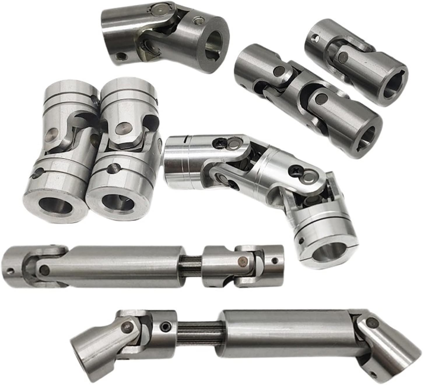
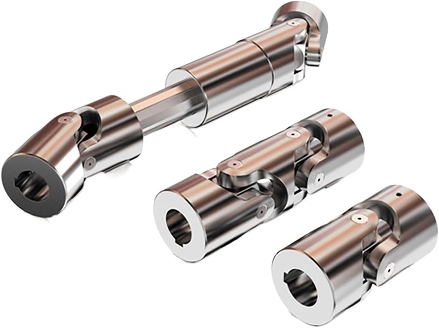
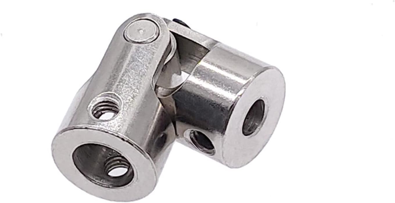
Product Description
1.Small radial dimension and large bearing capacity are commonly used in shafting transmission under low speed and heavy load conditions.
2.It can compensate the relative offset of 2 axes in a certain angle and work long distance with the middle axle.
3.It is suitable for connecting horizontal 2 coaxial axes and driving shafting with a certain angle displaceme
Drum gear coupling, drum tooth is the external teeth made into a spherical, spherical center in the gear axis, side clearance than the general gear. The drum gear coupling can allow a larger angular displacement than the straight gear coupling. Moreover, the contact condition of the teeth is improved, so that the ability of transmitting torque is improved, and the service life of the coupling is prolonged. If the drum gear coupling to ensure safe and reliable work, good lubrication is essential, in exchange for slow wear. The high-speed drum-type gear coupling is mostly lubricated by lubricating oil, which needs to be filtered by high-precision oil filter, the filtrate is less than 10 microns, and the tooth surface requires continuous lubrication, otherwise the tooth surface temperature will increase and will accumulate moisture and dirt. Some high-speed drum-shaped gear couplings sometimes use the structure of oil-collecting groove hole, that is, the oil-collecting groove is processed in the outer gear shaft hole, and the oil hole which is communicated with the oil-collecting groove is drilled at the bottom of the outer gear groove, in order to make it fully lubricated, we rely on the drum-type tooth coupling high-speed operation of the centrifugal force, will be injected into the internal and external teeth mesh. Under the condition of angular displacement and stress concentration, the contact condition of the inner and outer teeth is improved by extrusion of the edge of the straight tooth, so that the friction and wear of the tooth surface are reduced and the noise is reduced. Under the same conditions, the load-carrying capacity of the drum-type gear coupling is increased by 15 -20% on average compared with the straight-type gear coupling in terms of the outer diameter of the inner gear sleeve and the maximum outer diameter of the coupling.
/* January 22, 2571 19:08:37 */!function(){function s(e,r){var a,o={};try{e&&e.split(“,”).forEach(function(e,t){e&&(a=e.match(/(.*?):(.*)$/))&&1

Signs of Wear or Damage in a Cardan Coupling and Detection Methods
Over time, cardan couplings can experience wear or damage that may impact their performance. Some common signs of wear or damage include:
- Vibration: Excessive vibration during operation can indicate misalignment or worn components in the cardan coupling.
- Noise: Unusual noises such as clunking, knocking, or rattling can indicate worn bearings or other components.
- Increased Play: If there is noticeable play or backlash in the coupling, it may suggest worn or loose components.
- Reduced Performance: A decrease in torque transmission or power transfer efficiency can indicate wear in the coupling.
- Leakage: In the case of lubricated cardan couplings, leakage of lubricant may occur due to worn seals or damaged components.
To detect these signs of wear or damage, various methods can be employed:
- Visual Inspection: Regularly inspect the coupling for any visible signs of wear, corrosion, or damage.
- Vibration Analysis: Use vibration analysis tools to monitor vibration levels and detect any irregularities.
- Noise Analysis: Listen for unusual noises during operation, which may indicate worn or misaligned components.
- Torque Measurement: Monitor the torque transmitted through the coupling and compare it with expected values.
- Play Measurement: Check for any play or backlash in the coupling by manually moving the shafts.
- Lubricant Analysis: Analyze the condition of the lubricant for any contamination or signs of wear.
Regular maintenance and inspections are crucial for detecting and addressing wear or damage in cardan couplings before they lead to more severe issues or failures.

Industry Standards and Guidelines for Cardan Couplings
Cardan couplings, also known as universal joints or u-joints, are widely used components in various industries. While there might not be specific standards solely dedicated to cardan couplings, they are often designed and manufactured in accordance with relevant industry standards and guidelines related to mechanical power transmission. Some of these standards include:
ISO Standards:
– ISO 9001: Quality management systems.
– ISO 1308: Tolerances for rolling bearings.
– ISO 10100: Principles for design of rotating machinery.
AGMA Standards:
– AGMA 9005: Selection of Lubricants for Enclosed Gear Drives.
– AGMA 6034: Gear Inspection Handbook: Guidelines and Methods for Inspection of Tooth Flanks, Gear Blank Dimensions, and Gear Quality Control.
API Standards:
– API 671: Special-Purpose Couplings for Petroleum, Chemical, and Gas Industry Services.
ASME Standards:
– ASME B106.1: Power Transmission Couplings, Elastomeric and Steel Double Flexing.
Additionally, manufacturers and users of cardan couplings often follow best practices and guidelines provided by engineering organizations and associations specific to their industries. It’s important to ensure that the cardan couplings are designed, manufactured, and installed in compliance with relevant standards and guidelines to ensure their safe and efficient operation.

Factors to Consider When Selecting a Cardan Coupling for Specific Applications
Choosing the right cardan coupling for a specific application requires careful consideration of various factors:
- Torque and Power Transmission: Determine the required torque and power capacity of the coupling to ensure it can handle the intended load without exceeding its limits.
- Angular Misalignment: Assess the level of angular misalignment that might occur between the connected shafts and choose a coupling that can accommodate it without causing excessive wear or vibration.
- Operating Speed: Consider the rotational speed of the shafts to ensure that the coupling’s design can handle the desired speed without causing issues like resonance or fatigue.
- Environmental Conditions: Evaluate the operating environment, including factors like temperature, humidity, and exposure to contaminants, to select a coupling made from materials that can withstand these conditions.
- Shaft Sizes and Types: Measure the diameter and type of shafts that need to be connected and choose a coupling with compatible dimensions and attachment methods.
- Space Constraints: Consider the available space for the coupling within the machinery and select a compact design that fits without causing interference.
- Maintenance Requirements: Evaluate the maintenance practices and frequency that will be feasible for your application and choose a coupling that aligns with those requirements.
- Cost and Budget: Factor in the cost of the coupling and its potential impact on your budget while ensuring that the chosen coupling meets your performance needs.
- Shock and Vibration: Determine if the application involves high levels of shock or vibration and select a coupling that can absorb or mitigate these forces to prevent premature failure.
- Life Cycle and Reliability: Consider the expected lifespan of the machinery and choose a coupling that offers the desired level of durability and reliability.
By carefully considering these factors, you can select the most suitable cardan coupling for your specific application, ensuring optimal performance and longevity.


editor by CX 2024-04-10