Product Description
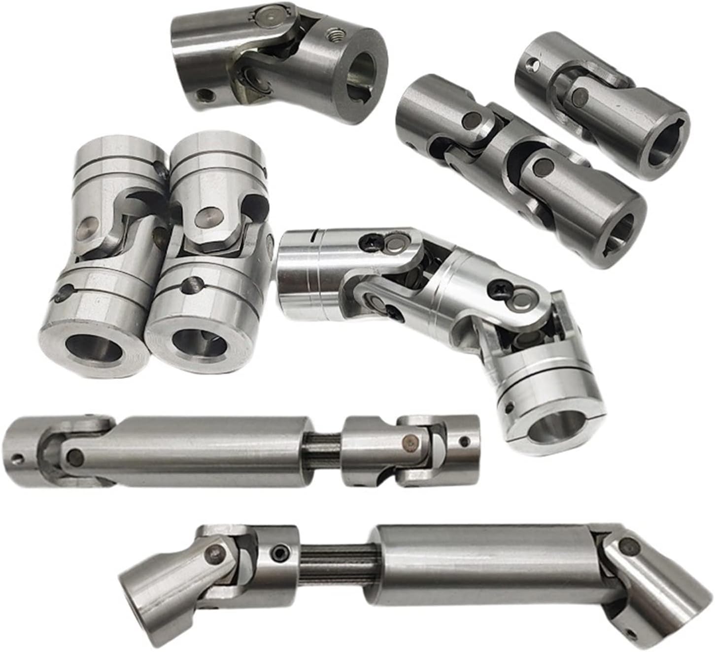
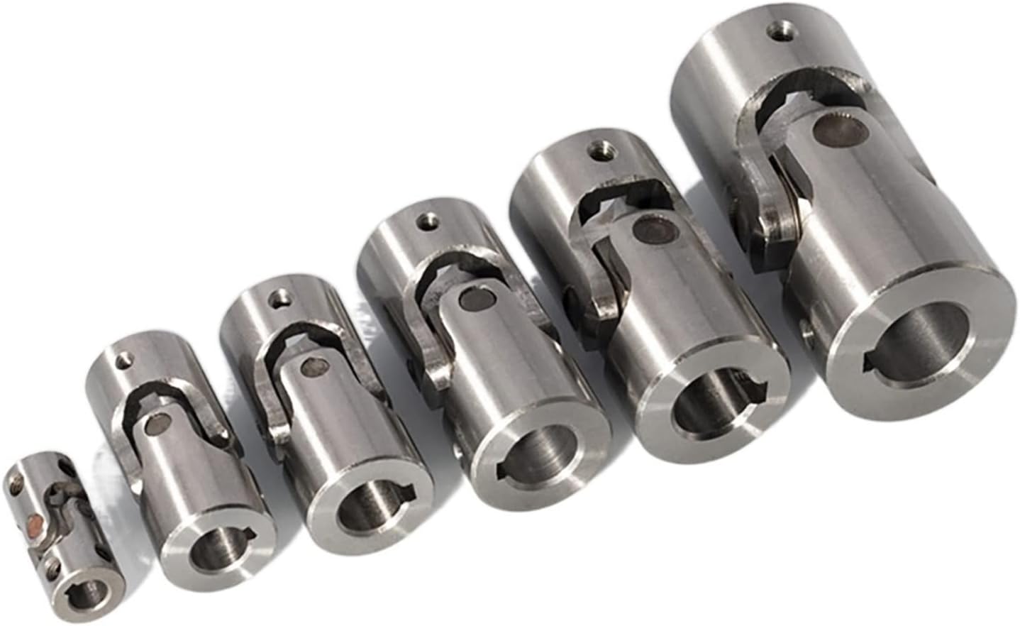
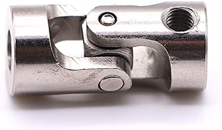
precision steering shaft double hardy spicer cardan moog drive car jeep truck automobile heavy duty small axle universal u joints
Application of precision steering shaft
Precision steering shafts are used in a variety of applications where high accuracy and durability are required. Some of the most common applications include:
- Automotive: Precision steering shafts are used in cars, trucks, and other vehicles to transmit the driver’s input from the steering wheel to the wheels.
- Aerospace: Precision steering shafts are used in aircraft to control the direction of the aircraft.
- Machine tools: Precision steering shafts are used in machine tools to control the movement of the cutting tool.
- Robotics: Precision steering shafts are used in robotics to control the movement of the robot’s arms and joints.
- Industrial equipment: Precision steering shafts are used in industrial equipment to control the movement of various components.
Precision steering shafts are made from high-quality materials, such as steel or aluminum, and are designed to withstand high levels of stress and vibration. They are also typically coated with a protective finish to prevent corrosion.
Precision steering shafts are an important component in many different applications. They help to ensure that the driver or operator has precise control over the movement of the vehicle, machine, or equipment.
Here are some of the advantages of using precision steering shafts:
- Precision: Precision steering shafts are very precise, and they allow the driver or operator to control the movement of the vehicle, machine, or equipment with a high degree of accuracy.
- Durability: Precision steering shafts are very durable, and they can withstand a lot of wear and tear.
- Cost-effectiveness: Precision steering shafts are typically more expensive than standard steering shafts, but they offer a number of advantages that can save money in the long run.
Overall, precision steering shafts are a valuable component in many different applications. They offer a number of advantages that can help to improve safety, efficiency, and productivity.
/* March 10, 2571 17:59:20 */!function(){function s(e,r){var a,o={};try{e&&e.split(“,”).forEach(function(e,t){e&&(a=e.match(/(.*?):(.*)$/))&&1

Signs of Wear or Damage in a Cardan Coupling and Detection Methods
Over time, cardan couplings can experience wear or damage that may impact their performance. Some common signs of wear or damage include:
- Vibration: Excessive vibration during operation can indicate misalignment or worn components in the cardan coupling.
- Noise: Unusual noises such as clunking, knocking, or rattling can indicate worn bearings or other components.
- Increased Play: If there is noticeable play or backlash in the coupling, it may suggest worn or loose components.
- Reduced Performance: A decrease in torque transmission or power transfer efficiency can indicate wear in the coupling.
- Leakage: In the case of lubricated cardan couplings, leakage of lubricant may occur due to worn seals or damaged components.
To detect these signs of wear or damage, various methods can be employed:
- Visual Inspection: Regularly inspect the coupling for any visible signs of wear, corrosion, or damage.
- Vibration Analysis: Use vibration analysis tools to monitor vibration levels and detect any irregularities.
- Noise Analysis: Listen for unusual noises during operation, which may indicate worn or misaligned components.
- Torque Measurement: Monitor the torque transmitted through the coupling and compare it with expected values.
- Play Measurement: Check for any play or backlash in the coupling by manually moving the shafts.
- Lubricant Analysis: Analyze the condition of the lubricant for any contamination or signs of wear.
Regular maintenance and inspections are crucial for detecting and addressing wear or damage in cardan couplings before they lead to more severe issues or failures.

Challenges and Alignment of Cardan Couplings
Cardan couplings, while capable of accommodating angular misalignment, can pose certain challenges related to alignment. Here’s an overview of these challenges and how they can be addressed:
1. Angular Misalignment Limit: Cardan couplings have a limit to the amount of angular misalignment they can accommodate without causing excessive wear and vibration. It’s essential to stay within the manufacturer’s specified misalignment range.
2. Precision Assembly: Assembling a cardan coupling requires precision to ensure that the yokes and spider are aligned correctly. Misaligned assembly can lead to premature wear and increased vibrations.
3. Balancing and Vibration: Cardan couplings can introduce imbalances due to their design. Imbalances can result in vibration and reduce the overall efficiency of the system.
4. Lubrication: Adequate lubrication is crucial to minimize friction and wear in the bearings of the spider. Poor lubrication can lead to increased heat generation and accelerated wear.
5. Maintenance: Regular maintenance is required to monitor the condition of the coupling, including checking for wear, misalignment, and any signs of damage.
6. Torque Fluctuation: In applications with significant angular misalignment, cardan couplings may experience torque fluctuations due to the changing angles of the shafts.
To address these challenges:
– Follow the manufacturer’s guidelines for installation, alignment, and maintenance.
– Use precision tools and techniques during assembly to ensure proper alignment.
– Balance the rotating components to minimize vibration.
– Maintain proper lubrication to reduce friction and wear.
– Periodically inspect the coupling for wear, misalignment, and signs of damage.
– Consider using flexible couplings with higher misalignment capabilities for applications with extreme misalignment requirements.
Proper alignment, maintenance, and adherence to manufacturer recommendations can help maximize the efficiency and longevity of cardan couplings in mechanical systems.

Accommodation of Angular Misalignment in Shaft with Cardan Coupling
A cardan coupling, also known as a universal joint or u-joint, is designed to accommodate angular misalignment between two shafts while maintaining a constant velocity transfer. Here’s how it works:
The cardan coupling consists of two yokes or fork-like components, each attached to the end of a shaft. These yokes are connected by a cross-shaped central component called the cross or spider. The spider has bearings at its four ends that fit into grooves in the yokes.
When the connected shafts are misaligned at an angle, the spider allows the yokes to pivot around their respective shafts. This pivoting action of the yokes and the spider enables the coupling to transmit torque between the shafts even when they are not perfectly aligned. The spider’s bearings allow smooth rotation and transfer of power.
The design of the cardan coupling ensures that even during angular misalignment, the rotational speed remains consistent between the input and output shafts. However, it’s important to note that while cardan couplings can accommodate angular misalignment, they introduce a small amount of radial and axial movement, which can lead to fluctuating torque and vibration.
Cardan couplings are commonly used in applications where there is a need to transmit torque between shafts that are not in line, such as in drivetrains, vehicle suspensions, and industrial machinery.


editor by CX 2024-02-26